A Machine Vision System Controlling the Cutting of Animal Hide
by Enrico Fantini, Fabio Ganovelli, Paolo Pingi
Based on the integration of image acquisition techniques and real-time systems, an innovative system for cutting raw hides has been developed at ISTI-CNR. The aim is to partly automate the cutting process, so that minimal human intervention is needed.
The current procedure for cutting animal hide is completely manual. The hide is spread out on a bench and expert operators decide the best cutting lines on the basis of the location of specific features. The hide is then manually cut using ad hoc knives and the parts are removed from the bench. The work of cutting the hide is the most time consuming step, and requires three or four workers.
Problem Specifications
Any system to support the cutting of animal skins needs to address the following operational parameters and conditions:
- the dimensions of raw hides can vary up to a maximum width and length of 3.5m
- the whole process should take less than one minute per hide, which is the time currently required by one skilled operator and three assistants
- the cutting system should work within a tolerance of approximately 1cm, measured as the maximal distance between the cuts performed and the ideal cuts. The error in terms of area should not exceed 2.0% of the total area - this is the tolerance allowed when the cutting is accomplished manually.
There are two main sources of error:
- the animal's coat visibly goes against the grain and either the operator does not spend enough time and attention on planning the cuts correctly or mistakes are made while cutting
- the ideal cutting lines of the flanks are not arranged symmetrically about the axis of folding. This error is essentially due to the working methodology since, to save time, the skin is folded in order to make two cuts at once.
To be commercially competitive, any automatic system must be at least as accurate as a human operator and possibly faster. The parameters above clearly define these acceptable levels of performance.
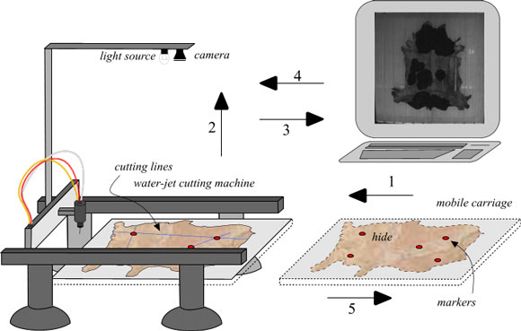 |
| Figure 1: The Cutting System. |
System Description
The system work cycle proceeds as follows:
- The skin is loaded by hand onto a mobile carriage and left unfolded. Reference marks are positioned on the skin and the carriage is started.
- A picture of the skin is taken by the camera.
- A computer vision module recognises the skin contour and marker positions and computes the cutting lines.
- The computed lines are transferred to a numerical control unit which controls the cutting.
- The carriage moves back to its initial position and the skin is unloaded.
Image Acquisition System Specifications
The image acquisition system is composed of a camera with suitable optics positioned 4.5m above the hide, a light source positioned near the camera, and the frame grabber.
These specifications are defined by the size of the area to be acquired (up to 3.5 by 3.5m), the limit on the height of the camera (at most 4.5m), and the required precision (0.5cm per pixel). The use of an 8.5mm lens allows these constraints to be met with the introduction of an acceptable distortion to the image.
In the calibration phase, the constants of radial distortion are found, along with the correspondence between the points in the image and the world coordinate. Calibration is only necessary after a hardware modification has occurred (eg if the relative position of camera, water-jet machine or carriage have changed).
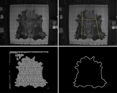 |
Figure 2: a) The input image; b) Cutting lines; c) detection of inside points; d) contour.
|
Computer Vision Module
This software module takes as its input the image acquired by the camera, and computes the cutting lines. These are completely specified by the skin contour and the markers’ position.
The markers are round-shaped pieces of common white paper, which show up brightly in the image and are distinguishable even on white skin. To detect the skin contour is harder because skins show wide variations in size, shape and colour. The software works on the difference between the carriage plane when it is empty and when the skin is present. More precisely, the carriage plane is made up of many white parallel bars. The empty space between the bars allows the water from the water-jet machine to flow away. Since the bars move under the weight of the loaded skin and also become soiled by the skins, pixel-by-pixel difference between images is not usable. Instead, the system uses an approach loosely based on Snakes (proposed by Kass et al) to detect the white bars, which are known to be present, and to classify the points where bar detection has failed as skin contour. Figure 2 shows the steps of the algorithm.
The process of acquisition and feature detection takes around 5 seconds to be performed. The time for the whole cycle is around 30 seconds.
Water-Jet Cutting Machine
The water-jet has a 0.35mm nozzle operating at a cutting pressure of 3 500 bar and a maximum cutting speed of 30m/min. The cutting bench incorporates specific mechanical modules and the conveyor belt.
The system described has been developed in cooperation with C.G.S. Sas - Ricerca Scientifica Avanzata, Pisa, within the framework of an EC project in the IST programme (IST1999-20188).
Please contact:
Paolo Pingi, ISTI-CNR
Tel.:+39 050 315 29 25
E-mail: paolo.pingi@isti.cnr.it
|