On-line Testing of the Reactor Protection System in the Paks Nuclear Power Plant
by István Varga, Tamás Bartha and Alexandros Soumelidis
The most important issue for safety-critical supervisory systems is the correct operation of every component. The Systems and Control Laboratory (SCL) of SZTAKI has developed a new validation and testing concept to ensure the correct functionality of safety elements. Three implementations have been completed and are regularly used in the Paks Nuclear Power Plant (Hungary).
Instrumentation and control (I&C) systems are used in safety-critical applications to monitor issues such as operational safety and service availability. They are gradually being replaced by software-based digital systems, and in order to enhance reliability in the design and operation phases of these software-based I&C systems, a number of techniques must be applied. One of the best-known of these is periodic testing during normal operation.
We have created a testing methodology for safety-critical supervisory systems, which has been implemented at the Paks Nuclear Power Plant located in Hungary. Each of four reactor units has a dedicated Reactor Protection System (RPS) for the intervention and safe shut-down of the unit in an emergency situation. This system contains three redundancies, also called 'trains'. An RPS, like all physical systems, is also susceptible to faults, including sensor failures and component hardware faults. Naturally, each RPS has a fault-tolerant, highly redundant hardware and software architecture. However, faults can cause latent errors that may become activated only in emergency conditions. To eliminate these and ensure reliable operation in all situations, an RPS must be periodically tested during normal operation by special test equipment.
The Test Concept
It is necessary that the test equipment be able to create experimental scenarios of input signals in one part of the protection system, without affecting the operation of the other parts or the RPS as a whole. While testing a certain train in a 2/3 redundancy system, only two trains remain in normal operation. This situation is very sensitive, since an error occurring in either of the two operating redundancies could initiate an emergency protection action. The train to be tested must be selected by a corresponding 'Test Enable' (TE) signal, while the TE signals of other trains are simultaneously disabled. During the test, the process parameters are set in such a way that safety actions are initiated.
The test execution makes the 2/3 redundancy system sensitive to errors. For this reason, the two trains not being tested are constantly monitored for errors during the test. If an error is detected in these systems, the test stop criterion disables the TE signal of the train being tested. This causes the test to cease immediately, and the train returns to normal operation. This ensures that two fault-free trains are always available for correct voting, and thus we avoid the activation of unnecessary EP actions.
The Test Equipment
The principles shown above have been implemented in the RPS of the Paks Nuclear Power Plant. We created three realisations of the test concept: test machines for the start-up and operational phases of the reactor (the Start-up Test Machine and Periodic Test Machine respectively), and an improved test system, which includes the complete functionality of the earlier machines (Universal Test System).
The periodic testing concept of the RPS system suggests a stand-alone Test Machine, which is temporarily connected to test inputs from the system in order to perform test procedures. However, a Periodic Test Machine designed and built on this basis proved inconvenient and difficult to use in practice. Therefore, the revised test concept includes a distributed, general-purpose test system called the Universal Test System, or UTS for short.
Universal Test System
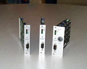
The basis of the distributed test equipment is an RS485-type industrial bus system (CAN), which provides the interface to the task-specific 'active' test plugs (analogue test plug, binary test plug, control plug etc; see Figure 2). The microprocessor-controlled analogue and binary active plugs contain all the devices necessary to perform a full test of the analogue and binary input modules. The active control plug contains transceiver and receiver components to send and receive control signals to/from the RPS system. The design of the active test plugs, the microcomputers and the RS485 bus interface requires implementation in high density SMD technology.
 |
 |
| Figure 1: Structure of the Universal Test System. |
Figure 2: UTS plugs. |
The active test plugs are powered by the RPS system. When all the safety requirements are equally satisfied, galvanic isolation must only be realised on the CAN interface. The analogue and binary plugs can be applied simultaneously to multiple input modules, even to a whole cabinet or a complete train. An industrial computer (Local Test Machine) controls the active test plugs using a CAN controller card. The Central Test Machine (CTM) supervises the three Local Test Machines, each of which is dedicated to a single RPS train, as shown in Figure 1.
 |
| Figure 3: The CTM software during a test. |
The Universal Test System is in regular use at the Paks NPP, and has helped to improve the reliability of the RPS system, while reducing the time, and therefore cost, dedicated to testing.
Link:
http://www.sztaki.hu/scl
Please contact:
Tamás Bartha, István Varga, SZTAKI
Tel: +36 1 279 6227
E-mail: bartha sztaki.hu, ivargasztaki.hu sztaki.hu, ivargasztaki.hu
|